When you are programming a robot, your aim is to make it as consistent as possible. Consistency applies to drivetrains for movement, but also to any actuators that you have on the robot such as claws, arms or other moving mechanisms. This post looks at how you can calibrate a mechanism as part of your code to improve accuracy.
These example are using IQ, but the same basic principles apply to GO, IQ, EXP and V5 although the values discussed would vary from platform to platform.
The first thing we need to establish is what we mean by calibration. For a mechanism to be consistent, there are a few key factors.
- Build quality - will not be discussed in detail in this post, but is worth noting. If the mechanism in question is of poor build quality and is unstable or has a lot of play in the system (the amount of travel before the motor starts to move) then it will be very difficult to code it to be consistent.
- Datum point – a known reference point that the mechanism will always start from. Without a datum to start from, the position that the mechanism moves to may be different every time.
Examples:
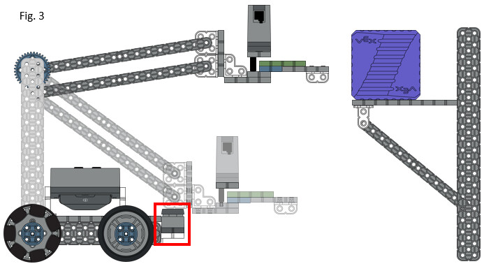
In Fig. 1 the datum (starting) point is as far down as the arm will go. We then move the arm up 45 degrees from that position to be able to grab the cube.
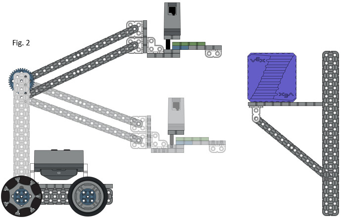
In a later match, we forget to ensure the arm is all the way down (Fig. 2), so now the datum is slightly higher to begin with. When the arm moves up 45 degrees, it is too high to collect the cube.
On the IQ Clawbot, this is very easy to overcome, you just need to remember to ensure the arm is all the way down to start with. But with more complex robots or mechanisms with very low gear ratios, moving it by hand might not be an option so we need to automate that process. Let’s stick with the Clawbot to show a couple of examples of how this can be done.
Bumper Switch
One option is to use the Bumper Switch to tell the arm when it is at the far end of the travel and therefore in the correct position. If you have a 3D printer or laser cutter in your workshop, you have probably seen something similar – when you power the machine on, the head moves in each direction hitting a limit switch at the end of each axis to set the datum points.
In Fig. 3, when the arm is all the way down, it presses the Bumper Switch. We can use this to set the zero position. This is what the code might look like:
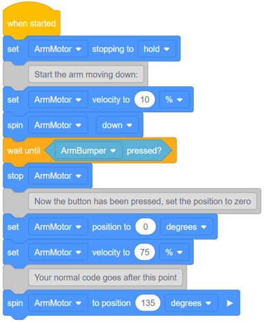
Let’s look at what is happening.
- First, we set the stopping mode to hold. This is good for an arm motor since it will hold the arm in the position that we instruct it to move to.
- Next we calibrate the arm. This can move quite slowly so the speed is set to 10%. Then, the arm is moved down until the bumper is pressed, then the arm is stopped.
- At this point, we set our datum by setting the current position to be zero degrees.
- Finally, we set the speed back to what will be used in the program.
When moving the arm, I like to use the spin to position command – that is because this position is always relative to zero, not to where the arm was last. (that’s a topic for a different post!)
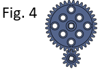
We spin it to 135 degrees because the Clawbot arm is geared at 3:1 (Fig. 4), so for the arm to move 45 degrees I need to rotate the motor three times that amount.
Current Sensing
Sometimes, there just isn’t space to fit a Bumper Switch in the mechanism, so here is another way that you can set a datum. This one relies on the mechanism having a solid “hard stop” at the end of the travel – i.e. something solid for the mechanism to hit when it reaches the end of its travel.
In this case, we can use a sensor that is built into the motor. VEX IQ (and GO, EXP and V5 motors) can tell us how much current they are drawing. The amount of current goes up when the motor is working harder.
We can use that information as a sensor because as the arm moves without any load (and especially with gravity on its side) it draws very little current. As soon as it hits the hard stop, the motor is stalled and the current goes up. We can use that to tell us when it hits the hard stop.
On an IQ motor, the current will be between 0 and 1.2 Amps.
Here is how we could use that principle in code to calibrate the arm:
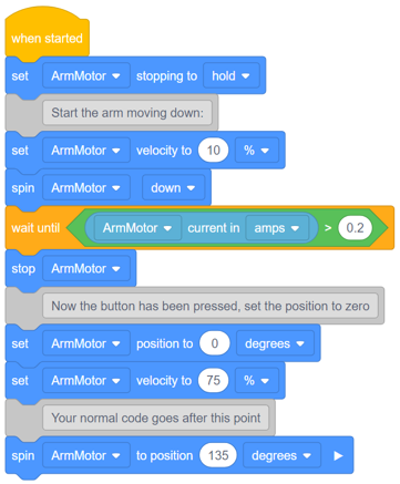
The code is pretty much the same as when using the Bumper Switch, but instead of waiting for the Bumper to be pressed, we wait for the current to go above 0.2A. You will need to fine-tune that figure based on your mechanism – too low and the current will go above this before you reach the end stop. Too high, and the motor might be pushing too hard against the end stop and break something. Start low and work up.
Happy coding!

