Hello,
I am currently working through the Ring Leader STEM Lab with my Intro to Robotics classes. Students have been making programs for the autonomous part of picking up a ring and scoring it on the post. One thing I’ve noticed that is giving a lot of groups trouble is the consistent accuracy of how the drivetrain turns and drives.
Most of my groups have made significant modifications to the standard Clawbot as part of previous activities we have done. So it’s possible that things like changes in weight or using different wheels is affecting how the robots drive. I’ve suggested a few times that they make use of the built-in inertial sensor by using [turn to heading] instead of [turn for]. This seems to help with turning (usually), but there’s still some inconsistency with the distance driven.
I tried looking up exactly how the [drive for] is calculated, but couldn’t find a good answer. Is it based on number of rotations? I want to be able to give my students some suggestions that could help improve their robot’s consistency.
1 Like
Hi Leo!
First of all, I’m so excited to hear that you and your students are working through the Ring Leader STEM Lab! Based on what you’re describing, my first thought is checking the wheel sizes on the physical build compared to the Drivetrain Settings in VEXcode.
Are students using the Clawbot example project? This template pre-configures the drivetrain.
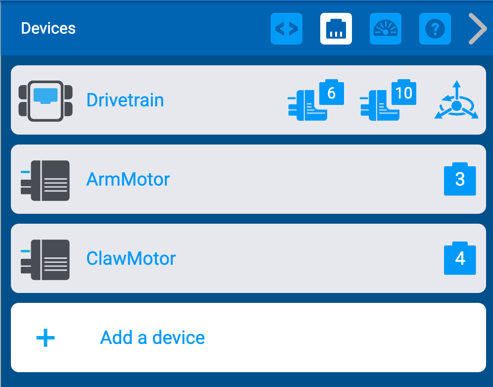
When you open this template and then select the plug icon in the top right, you can see the device configurations.
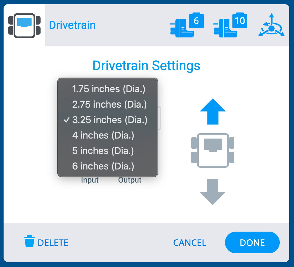
From there, when you select “Drivetrain” you can see what the left and right motor as well as the inertial sensor are plugged into (which port number). You can also see the gear ratio and the wheel size. I’m assuming that students have not added any gears to their drivetrain, but if they did, they could adjust that ratio here. I am wondering about the wheel size. The standard size is 3.25 inches.
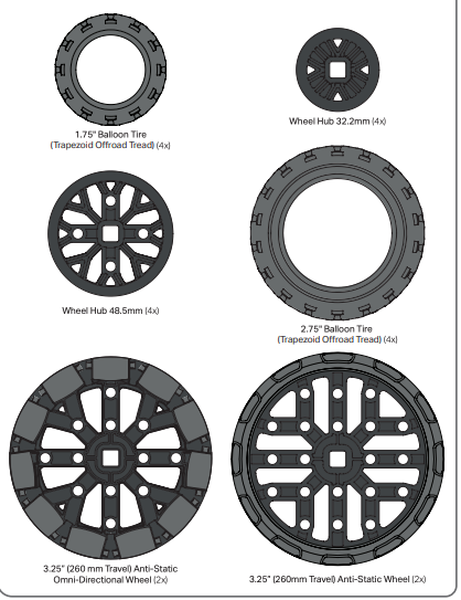
You can find the different wheel sizes on the parts poster.
To answer your earlier question, [drive for] is calculated using the size of the wheel and the number of rotations. So, if the block is programmed for the drivetrain to travel 6 inches, the math behind the block would be taking the distance desired to travel, the size of the wheel (in circumference), and then calculating the number of rotations needed to travel that distance. In other words, the formula would be distance = circumference x turns. I explain this in more detail in the “Mathematics of Driving” video found on this page. Even though this is a GO resource, the math behind how the driving works is the same 
I will also say, the blocks in that video show [spin for] blocks, which just controls one motor per block. The difference for the [drive for] blocks, is that single block controls both motors or all wheels connected to the drivetrain. However, the main math concept behind how it works is the same.
Let me know if this helps and I’m looking forward to hearing more about how you and your students progress through the Ring Leader STEM Lab! 
2 Likes