Hi everyone! Thank you to those that attended my Using the AI Vision Sensor with VEX CTE workshop at the 2026 VEX Robotics Educators Conference last week!
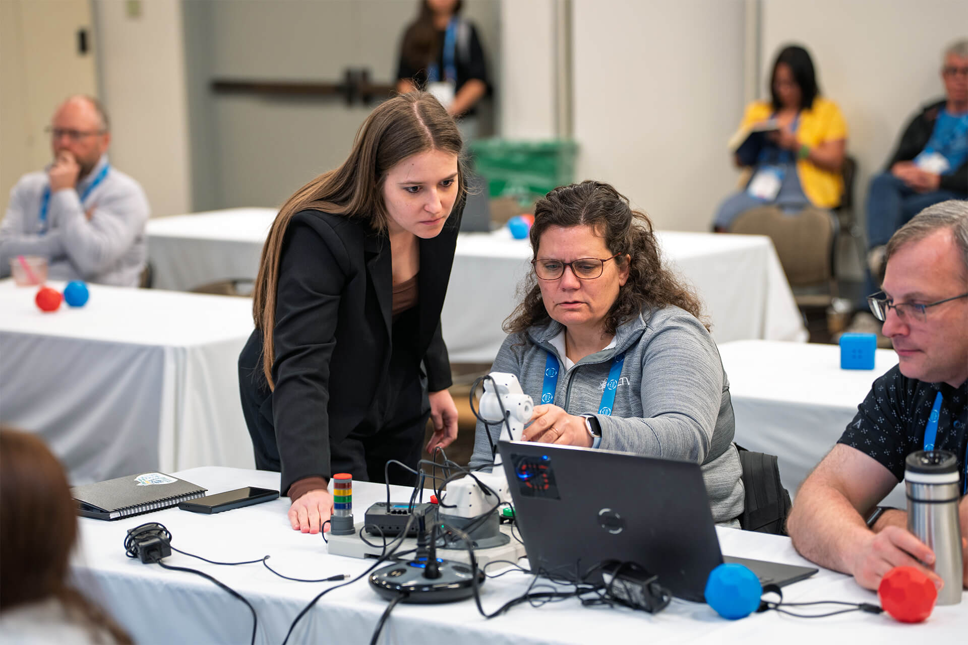
I mentioned during the workshop that I would post a PDF of my slides and the project file we coded together. Here is the PDF of the slides:
Using the AI Vision Sensor with VEX CTE.pdf (1.8 MB)
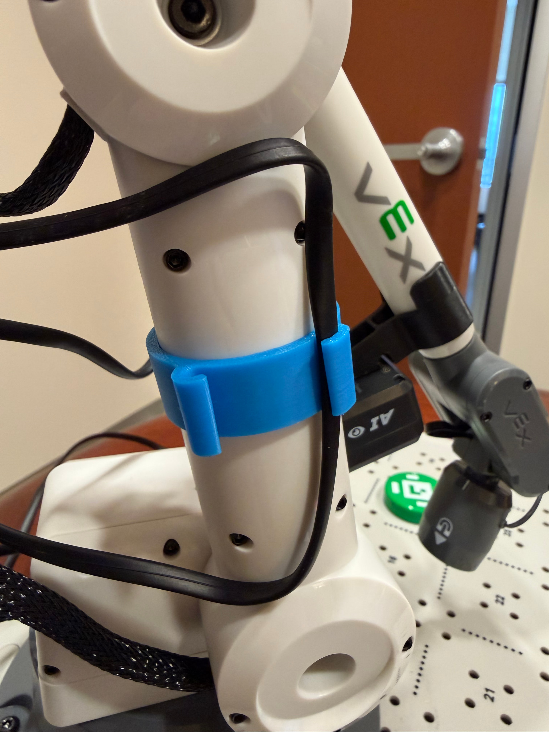
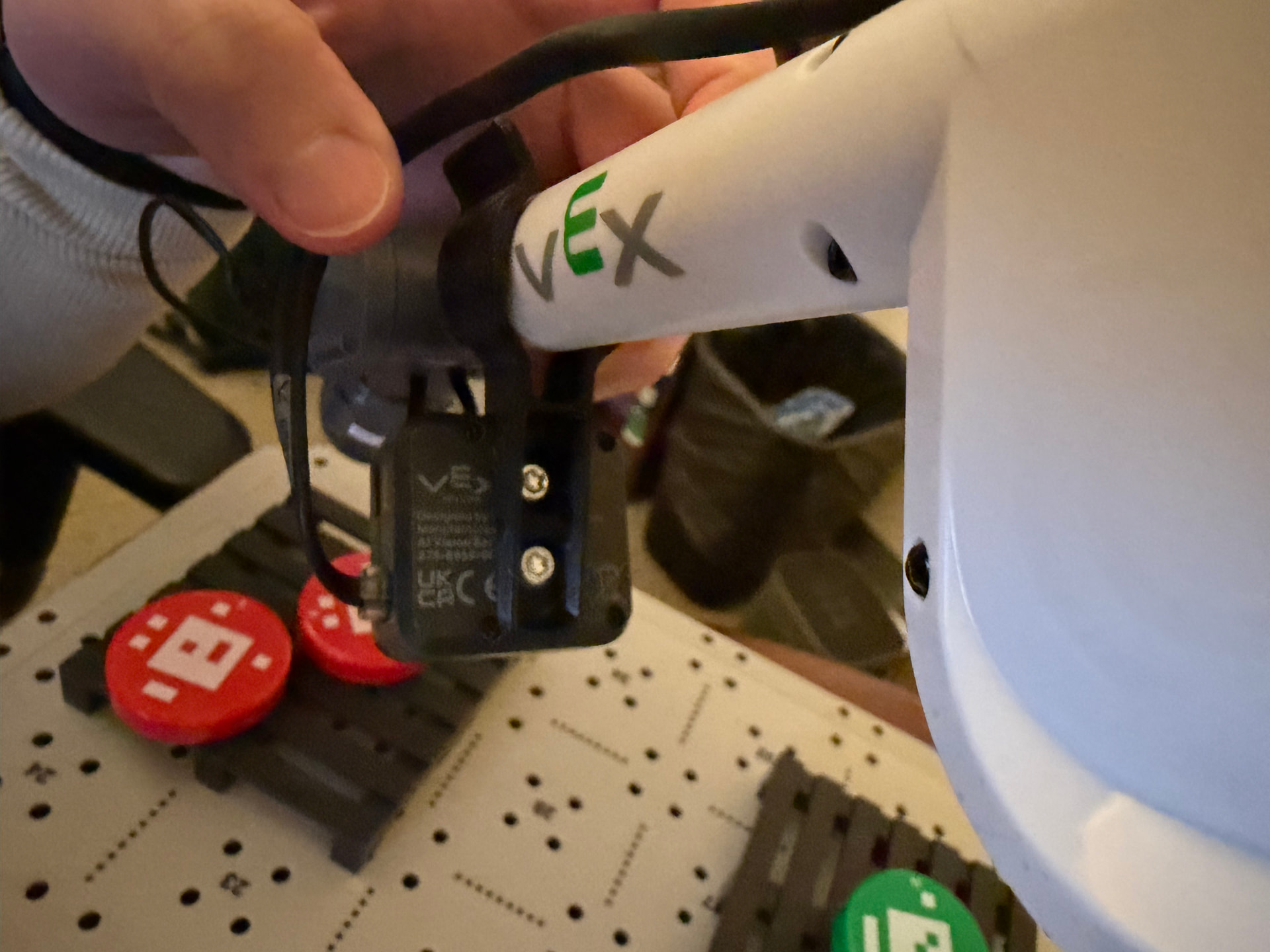
One of the most exciting parts of this workshop is that we got to use beta AI Vision Sensor mounting parts on the CTE arm! The two main parts that we used is the actual AI Vision Sensor mount and then a cable mount. Here are some images to show where those parts are located on the arm itself. I used two 8-32 x 0.250" Locking Star Drive Screws with 8-32 Low Profile Nuts to secure the mount to the AI Vision Sensor.
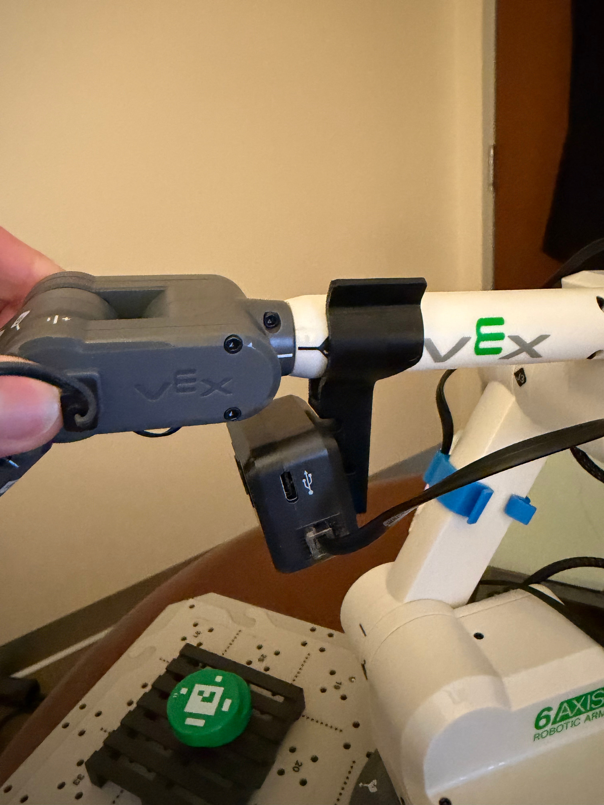
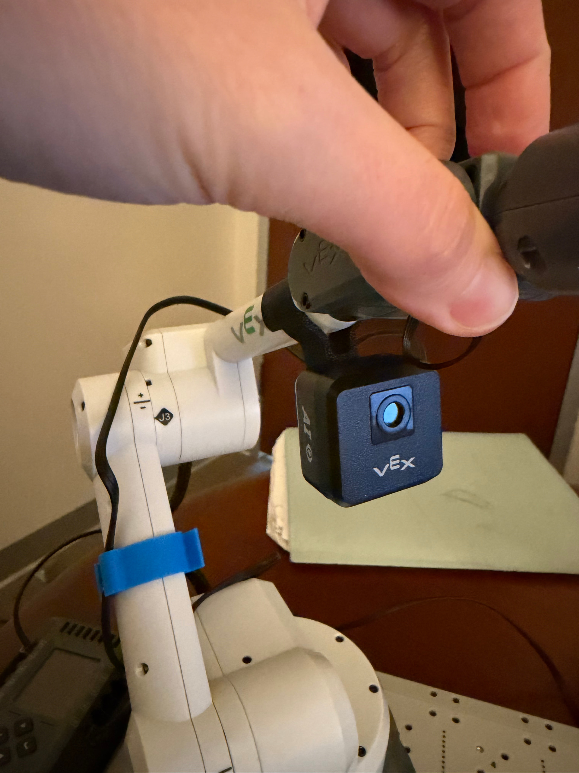
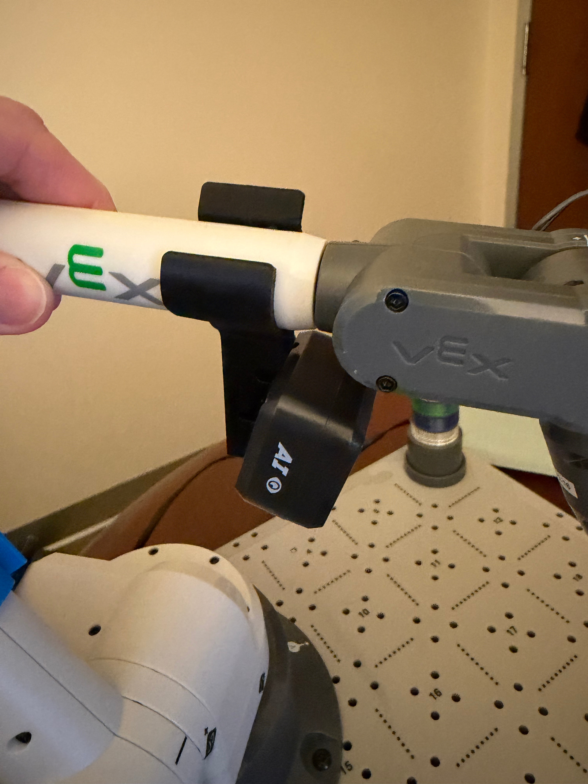
Here are the beta .STEP files for the arm and cable mounts. These are currently in development, but I’m excited to share them with you in case you’d like to 3D print them and test them yourself.
CTE AI Vision Cable Mount.STEP (1.5 MB)
CTE AI Vision Arm Mount.STEP (1.0 MB)
During the workshop, we did the Field of View activity to better understand that the AI Vision Sensor sees when it is mounted on the CTE arm. I wanted to provide the steps for the this activity in case you’d like to do it yourself.
Field of View Activity
- Ensure the AI Vision Sensor is mounted on the CTE arm using the arm mount.
- Follow the steps in this article to connect the AI Vision Sensor and open the Utility.
- Ensure you can see the live stream of what the sensor sees in the Utility.
- Take any object (like a disk) and move it around the sensor to see where the edges of its field of view are.
- Use painters tape or pipe cleaners to map where the edges of the field of view are.
- Move the arm around (from side to side or up and down) and notice that as you do so, the field of view changes.
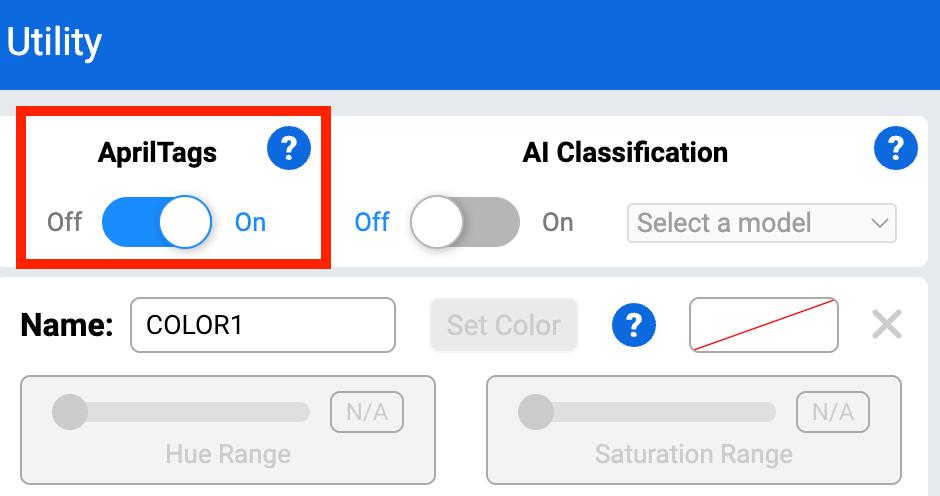
- Make sure to toggle the “AprilTags” on before closing the Utility. This will be used later in the coding project.
More information about the AI Vision Sensor can be found in this category of the VEX Library.
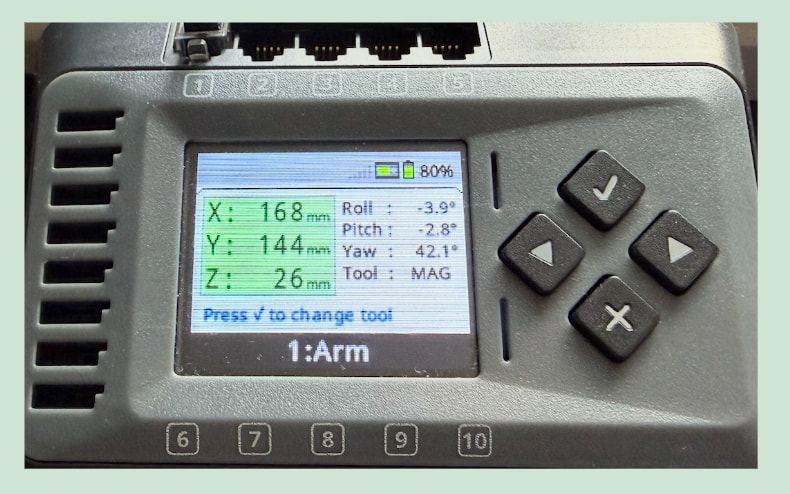
After we worked through the Field of View activity to better understand what the AI Vision Sensor sees, we explored how the arm moves in 3D space. To do this, we opened the “Arm” option through the Devices screen. More information on how to access the Devices screen can be found in this article.
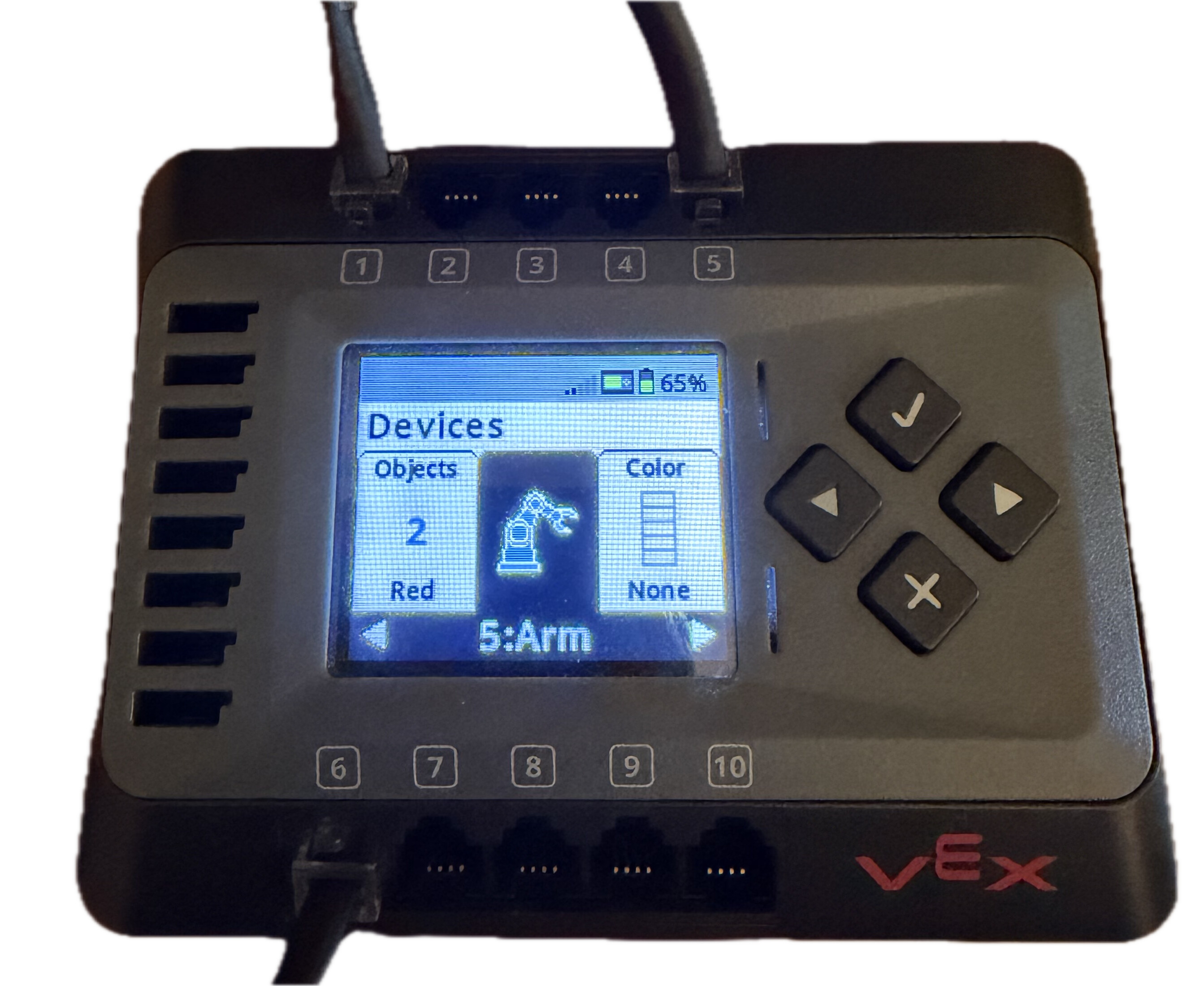
Once “Arm” was selected, the current x, y, z-coordinates display on the Brain’s screen and change in real time as the arm moves around. One of the biggest takeaways is that the AI Vision Sensor sees in pixels, while the arm moves in 3D space.
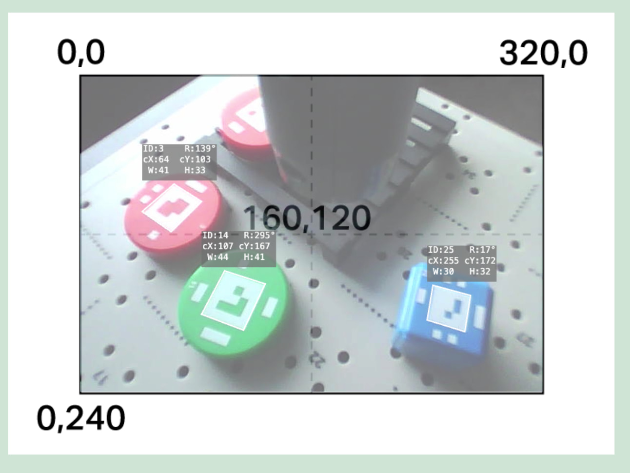
So, how can we combine these two different units of measurement? We worked through a project that had the CTE arm (with the AI Vision Sensor mounted), scan the tile for an object (disk), align the x and y-axes to the disk, lower the z-axis of the arm to grab the disk using the magnet, then place the disk on one of the two pallets depending on the color of the disk (red or green). Here is a video of the project running and a green disk being placed on one of the two pallets.
During the workshop, I worked through building the code for this project in stages. Here is the link to the full project file. Please note that the disk should be placed on tile number 17 when testing.
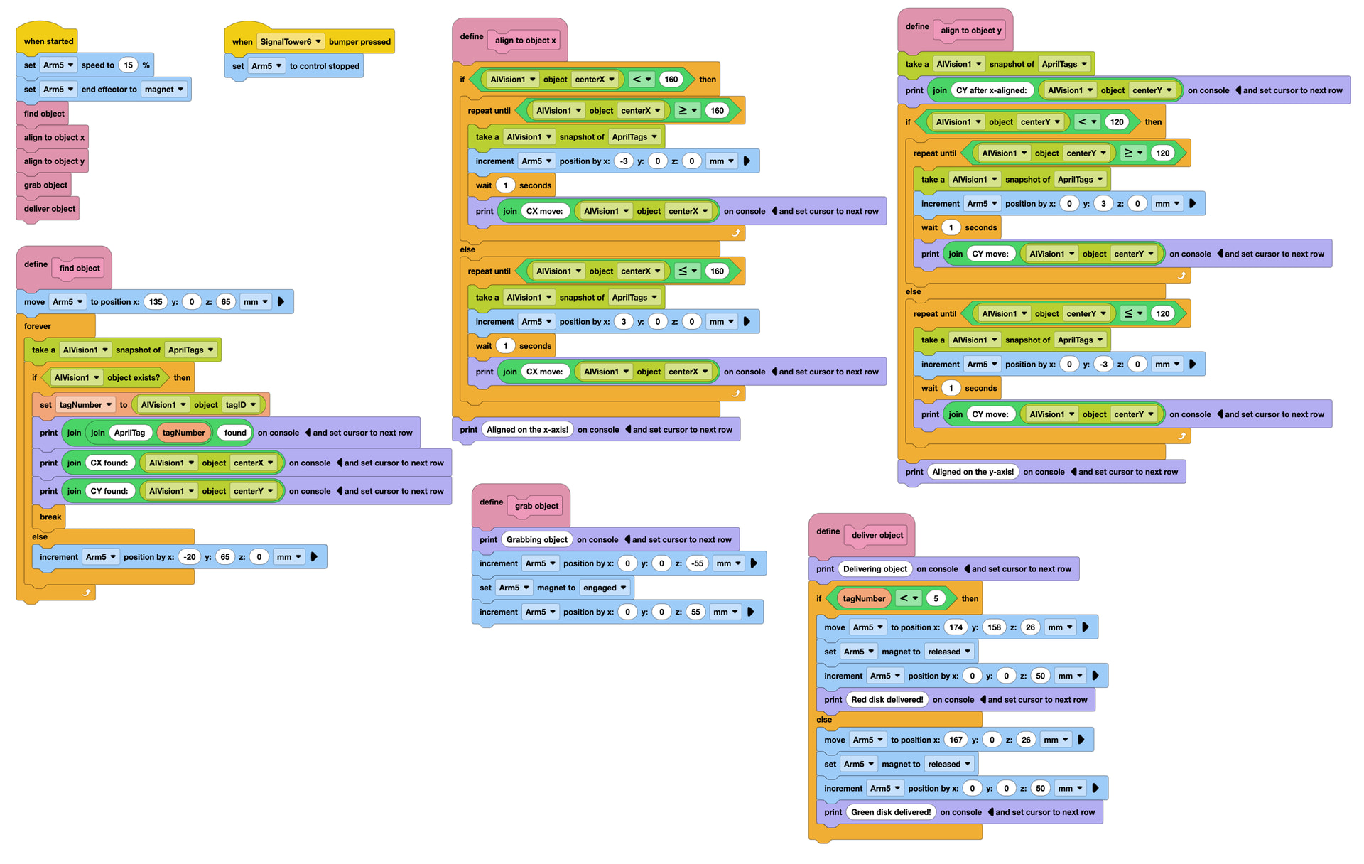
AI Vision CTE.expblocks (27.8 KB)
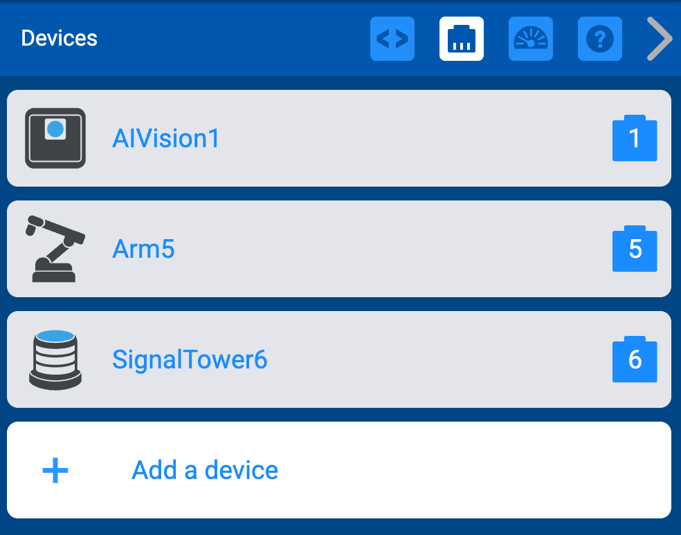
In order for this code to work correctly, all components should be configured as follows:
- Arm: Port 5
- AI Vision Sensor: Port 1
- Signal Tower: Port 6
Overall I had so much fun in this workshop and can’t wait to hear what you think of these materials! ![]()
